Category: Geospatial Projects

  • End-to-end GeoAI with TorchGeo

    End-to-end GeoAI with TorchGeo

    This post is part of my portfolio of personal projects resulting from my transition from generalist data science (2013-2025) to geospatial data science, GIS, and GeoAI (2025+).

    Using a segmentation neural network to detect objects in satellite raster data is now a fairly common GeoAI use case, and can be done in a broad-brush sense with no-code or low-code tools. Finer-grained control of the model, data, and processing is often still desirable for real end-to-end analyses, however. The TorchGeo tool builds upon PyTorch and PyTorch Lightning to enable end-to-end GeoAI for a wide range of use cases. We show how plain PyTorch code is augmented by Lightning’s data and model modules, then in turn by TorchGeo’s geospatial functionality. This lets us run end-to-end building detection as an example, and control the details.

    GeoAI and the cloud are the next frontiers of GIS and geospatial data science, allowing powerful analyses not previously possible.

    Here we train and use a model to detect buildings in the Inria data supplied with TorchGeo. While the data and functions can largely be used as black boxes, it is informative to show how TorchGeo is building on several layers of capabilities to make end-to-end GeoAI as tractable as it is here.

    We cover

    • PyTorch neural network with DataLoader, training loop, etc.
    • PyTorch Lightning with Data and Model modules
    • TorchGeo instantiations of these modules for Inria data
    • TorchGeo calling of these for end-to-end data preparation, model training, and inference

    The code to run this end-to-end is available in this project’s GitHub repository.

    Setup

    End-to-end GeoAI in exploratory as opposed to production mode is a workflow that benefits from being able to combine code, data visualization, and commentary inline. In other words, it is helpful to use a modern form of literate programming commonly known as a Jupyter notebook.

    We use the VS Code IDE which allows Python and Jupyter to be run within a virtual environment, along with the functionalities of debugging, inline class documentation, AI coding assistance, etc.

    AI assistance in particular can help rapidly prototype code that is approximately syntactically correct. But it still in general needs to be refined to be 100% what we want, especially in terms of doing the correct analysis. Similarly to a built-in LLM model generating code, an AI agent could potentially be prompted to do the whole analysis, but the same issues of code and analysis correctness would be encountered, with errors potentially extending end-to-end rather than over one notebook cell.

    A Python virtual environment .venv is created, within which we can install TorchGeo using their preferred pip install torchgeo route. This in turn brings in the needed dependencies of PyTorch, PyTorch Lightning, and other libraries. VS Code’s Python and Jupyter extensions enable notebook use.

    The author’s Mac laptop has an Apple M3 Max processor with GPU, and since our purposes here are exploratory and pedagogical it was not necessary to access cloud-scale GPU resources to run things. Amazon EC2 was accessed, but it quickly became apparent that modern GPUs such as A100 or H100 were in short supply. Providers such as Lambda, CoreWeave, or DigitalOcean would be alternative options if we wanted to pursue the cloud, along with geospatial tiling tools to run things at scale.

    Similarly, because the data are not large, we download it to local disk rather than accessing remote storage such as an Amazon S3 cloud bucket.

    Geospatial machine learning

    Most machine learning is designed to work with either tabular data, textual data, or images. For geospatial, two main modifications are needed:

    • Spatial awareness of models w.r.t. the images or other information
    • Handling color images with more channels than the usual red, green, and blue (RGB)

    This means that most non-geo tutorials won’t work as-is with geo data, and need modifying at the code level. Changes include handling images within the data loader, the model architecture, the training loop, and inference.

    A major benefit of TorchGeo is that it streamlines these modifications, while remaining open source with the underlying code visible. This enables geo data to be used end-to-end in the PyTorch ecosystem without having to write the code from scratch, but in a manner that can be understood as opposed to a black box.

    Building up to Torchgeo

    It is instructive to build up to what TorchGeo is doing by looking at a typical model in PyTorch, followed by PyTorch Lightning, and then TorchGeo.

    PyTorch

    The basics of end-to-end usage of a model are well illustrated by the tutorial quick-start in the PyTorch GitHub repository. Let’s run through the code, with an eye on our upcoming geo end-to-end analysis. (Quoting the code here is allowed by the repository’s LICENSE file.) This model runs a small neural network on the classic non-geo dataset Fashion MNIST, essentially a “hello world” end-to-end.

    Assuming everything is installed (TorchGeo will bring in these dependencies), import the needed modules from PyTorch and TorchVision:

    import torch
    from torch import nn
    from torch.utils.data import DataLoader
    from torchvision import datasets
    from torchvision.transforms import ToTensor

    Download the data. Fashion MNIST is a built-in TorchVision dataset, hence datasets:

    training_data = datasets.FashionMNIST(root="data", train=True, download=True, transform=ToTensor())
    test_data = datasets.FashionMNIST(root="data", train=False, download=True, transform=ToTensor())

    This gives us the data as a Dataset object, in tensor format suitable for a model. It also has metadata about whether it is used for training, and thus has labels, or testing.

    When a model is trained, it is not given all the data at once, so Dataset objects are wrapped with a DataLoader. This iteratively goes through the Dataset to pass it to the model, and handles other needed operations such as randomizing the order of the rows.

    batch_size = 64
    train_dataloader = DataLoader(training_data, batch_size=batch_size)
    test_dataloader = DataLoader(test_data, batch_size=batch_size)
    for X, y in test_dataloader:
        print(f"Shape of X [N, C, H, W]: {X.shape}")
        print(f"Shape of y: {y.shape} {y.dtype}")
        break

    The for loop shows us the data shape so we know that it is what it should be: N images, C channels, each image of height H and width W. This is important for geo data since there will often be more channels than the usual 3 in RGB color images.

    Now we define the model. When using pure PyTorch like here, this is done by creating a model class which subclasses the nn.module class. We can therefore see the full model architecture and change any details if we need to. The device line puts the model onto a GPU if one is available.

    device = torch.accelerator.current_accelerator().type if torch.accelerator.is_available() else "cpu"
    print(f"Using {device} device")
    
    class NeuralNetwork(nn.Module):
        def __init__(self):
            super().__init__()
            self.flatten = nn.Flatten()
            self.linear_relu_stack = nn.Sequential(
                nn.Linear(28*28, 512),
                nn.ReLU(),
                nn.Linear(512, 512),
                nn.ReLU(),
                nn.Linear(512, 10)
            )
    
        def forward(self, x):
            x = self.flatten(x)
            logits = self.linear_relu_stack(x)
            return logits
    
    model = NeuralNetwork().to(device)
    print(model)

    The network is defined by __init__, and how the data passes through is defined by forward.

    The model is then part of the training loop, which passes the data forward through the model, and the model weights are updated by the backward pass shown below. The model is performing well when the weights are such that the error on its predictions of the labels in the testing set, the loss, is minimized.

    The model is put through the training loop a number of times, or epochs, and so we have the train() and test() functions, and a loop on epochs.

    Training:

    loss_fn = nn.CrossEntropyLoss()
    optimizer = torch.optim.SGD(model.parameters(), lr=1e-3)
    
    def train(dataloader, model, loss_fn, optimizer):
        size = len(dataloader.dataset)
        model.train()
        for batch, (X, y) in enumerate(dataloader):
            X, y = X.to(device), y.to(device)
    
            # Compute prediction error
            pred = model(X)
            loss = loss_fn(pred, y)
    
            # Backpropagation
            loss.backward()
            optimizer.step()
            optimizer.zero_grad()
    
            if batch % 100 == 0:
                loss, current = loss.item(), (batch + 1) * len(X)
                print(f"loss: {loss:>7f}  [{current:>5d}/{size:>5d}]")

    Testing:

    def test(dataloader, model, loss_fn):
        size = len(dataloader.dataset)
        num_batches = len(dataloader)
        model.eval()
        test_loss, correct = 0, 0
        with torch.no_grad():
            for X, y in dataloader:
                X, y = X.to(device), y.to(device)
                pred = model(X)
                test_loss += loss_fn(pred, y).item()
                correct += (pred.argmax(1) == y).type(torch.float).sum().item()
        test_loss /= num_batches
        correct /= size
        print(f"Test Error: \n Accuracy: {(100*correct):>0.1f}%, Avg loss: {test_loss:>8f} \n")

    Epochs:

    epochs = 5
    for t in range(epochs):
        print(f"Epoch {t+1}\n-------------------------------")
        train(train_dataloader, model, loss_fn, optimizer)
        test(test_dataloader, model, loss_fn)
    print("Done!")

    When the model has been trained we want to save it:

    torch.save(model.state_dict(), "model.pth")
    print("Saved PyTorch Model State to model.pth")

    Often when training large models, intermediate steps called checkpoints are saved during training so that if something goes wrong the run does not have to be restarted from the beginning.

    Now that there is a trained model, we want to perform the step that many tutorials and articles do not cover: apply the model to new data!

    PyTorch can do this in a simple way by using eval

    model = NeuralNetwork().to(device)
    model.load_state_dict(torch.load("model.pth", weights_only=True))
    
    classes = ["T-shirt/top", "Trouser", "Pullover", "Dress", "Coat", "Sandal", "Shirt", "Sneaker", "Bag", "Ankle boot"]
    
    model.eval()
    x, y = test_data[0][0], test_data[0][1]
    with torch.no_grad():
        x = x.to(device)
        pred = model(x)
        predicted, actual = classes[pred[0].argmax(0)], classes[y]
        print(f'Predicted: "{predicted}", Actual: "{actual}"')

    Here the new data still has labels, but is not required to.

    In a production system, the trained model can be deployed on a server, and be run on new incoming data, i.e., inference.

    PyTorch Lightning

    From the above we see that we need to

    • Obtain the data
    • Prepare the data
    • Define a data loader
    • Define the model
    • Run the training loop
    • Evaluate the model
    • Run inference on new data

    PyTorch Lightning is designed to modularize and streamline this process so that the code remains manageable when the functionality of the basic model above is extended to more complex data and models.

    Geo data will have changes from non-geo data in all of the above steps, so Lightning is a big plus for handling all of the necessary processing.

    Lightning’s modularization is in the form of

    • Dataset: Type (e.g., raster), file locations, plots, etc.
    • Data module: Data preprocessing and loading into the model
    • Lightning module: Which training task to run: classification, segmentation, etc.
    • Trainer: Model settings for training
    • Trainer.fit: Run training (validation, testing also available)
    • Trainer.predict: Run inference on new data

    Schematically, this looks like

    dataset = DatasetName(files, ...)
    datamodule = DatasetNameDataModule(dataset, ...)
    task = NeuralNetworkModel(model, settings, hyperparameters, ...)
    trainer = Trainer(model settings)
    trainer.fit(task, datamodule, ...)
    trainer.predict(task, datamodule, ...)

    This allows different combinations of datasets and models to be run without having to rewrite a lot of code.

    TorchGeo

    TorchGeo in turn uses the PyTorch Lightning modular approach and supplies ready-made dataset, data loader, and model modules for many geospatial datasets. It also includes various library functions to ease the geospatial processing components of this, such as combining images of parts of an area (common because images are large) into a larger image of the whole area.

    So in TorchGeo we have

    • Datasets: PyTorch dataset, geo or non-geo, raster or vector, etc., from curated or customizable sources
    • Data modules: Download data and create a DataLoader for a specific geo dataset with appropriate splits such as train/test in non-overlapping geographic areas
    • Models: ML models that have appropriate architecture and good performance with geo data
    • Trainers: Run a given ML model to perform a given task, such as classification, segmentation, etc., followed by inference

    There are many further features like custom losses, samplers that take into account bounding boxes, and transforms to add geo featurizations to data such as vegetation indices. The geo processing functions can then do things like combining Datasets.

    It is this as a whole which allows us to say let’s run the U-Net segmentation model on the Inria Aerial Image Labeling dataset to detect buildings, and then apply it to some unseen data, without it being a major project. But we retain access to the details given by the full code, rather than their being hidden behind a low- or no-code interface. Such interfaces are great if they do exactly what you want, but they become much less useful if they don’t, and often completely opaque if there is an error.

    Running the building detection model

    Now we have an overview of how everything works, let’s run the building detection model. For the full code, see this project’s GitHub repository.

    Define the model task we want to run

    task = SemanticSegmentationTask( # SemanticSegmentation in 0.10+
        model='unet',
        backbone='resnet50',
        weights=True, # Use existing pretrained ImageNet weights
        in_channels=3, # RGB
        task='binary', # 2 classes building and not-building
        loss='bce', # TorchGeo 0.9+ adds pos_weight and Dice loss
        freeze_backbone=True, # Freeze encoder and train decoder + head
        lr=0.001 # Learning rate
    )

    Choose the data we want to use, the ready-defined data module Inria

    datamodule = InriaAerialImageLabelingDataModule(
        batch_size=1, # Large batches go out of memory on M3 laptop
        patch_size=1024,
        num_workers=2,
        root=data_dir
    )

    Here, batch_size is how many training examples are passed to the model each time around the training loop. We used a batch size of 1 due to memory limitations on the laptop. The data module breaks up each of Inria’s 5000×5000 pixel TIFF images into smaller patches of, e.g., 64×64 pixels that can be passed through the model.

    Log and visualize the training using TensorBoard, helpful for, e.g., checking that the validation loss doesn’t start becoming worse than the training loss (overfitting):

    %load_ext tensorboard
    logger = TensorBoardLogger(save_dir=experiments_dir, name='inria_logs')
    %tensorboard --logdir "$experiments_dir"

    Set model and early stopping checkpoints. These provide safety against having to rerun the model from scratch, and the training going on for too long, respectively. Early stopping is mostly illustrative as we do not run for many epochs on the laptop, although it did get invoked in the final results we show below.

    checkpoint_callback = ModelCheckpoint(
        monitor='val_loss',
        dirpath=experiments_dir,
        save_top_k=1, # Save best model
        save_last=True,
        mode='min' # Minimize the monitored quantity (val_loss)
    )
    
    early_stopping_callback = EarlyStopping(
        monitor='val_loss',
        min_delta=0.0,
        patience=10, # Stop if not significant change after this many epochs
        mode='min',
        strict=True,
        check_finite=True
    )

    Set up the model trainer

    trainer = Trainer(
        accelerator='auto', # Can see gpu or mps on Mac
        callbacks=[checkpoint_callback, early_stopping_callback],
        default_root_dir=experiments_dir,
        fast_dev_run=fast_dev_run,
        max_epochs=20,
        limit_train_batches=frac_subsample,
        limit_val_batches=frac_subsample,
        limit_test_batches=frac_subsample,
        limit_predict_batches=frac_subsample,
        log_every_n_steps=1,
        logger=logger
    )

    where frac_subsample < 1 can be used for faster sanity-check runs, max_epochs can be set, and accelerator automatically puts the model on the GPU.

    Training, model validation, and predictions (inference) on unseen data can then be run in one line each:

    trainer.fit(model=task, datamodule=datamodule)
    results_val = trainer.validate(model=task, datamodule=datamodule)
    preds = trainer.predict(model=task, datamodule=datamodule)

    Viewing the Results

    In principle that gives us all our results. Of course, we want to view them, and this takes some more coding. Writing ready-made user classes for such visualization is less convenient than preprocessing or training because the exact form of predictions from the model depend on the data, the model, and all the settings.

    Nevertheless, TorchGeo still reduces the coding to some extent by supplying generic functionality such as a plot method in the Inria data module to show samples of images.

    The Inria data consists of the training set of 155 images:

    AreaNo. ImagesIndicesFilename (.tif)
    Austin, TX310-30austin
    Chicago, IL3131-61chicago
    Kitsap county, WA3162-92kitsap
    West Tyrol, Austria3193-123tyrol-w
    Vienna, Austria31124-154vienna

    the validation set of 25 images:

    AreaNo. ImagesIndicesFilename (.tif)
    Austin, TX50-4austin
    Chicago, IL55-9chicago
    Kitsap county, WA510-14kitsap
    West Tyrol, Austria515-19tyrol-w
    Vienna, Austria520-24vienna

    and the testing set of 180 images:

    AreaNo. ImagesIndicesFilename (.tif)
    Bellingham, WA360-35bellingham
    Bloomington, IN3636-71bloomington
    Innsbruck, Austria3672-107innsbruck
    San Francisco, CA36108-143sfo
    East Tyrol, Austria36144-179tyrol-e

    The testing set areas are not in the training or validation sets.

    Note that the indices come in the order of the image filenames, which differ from the areas themselves. It always pays to check the data!

    For more information about the Inria dataset, see the original paper.

    Input data images can be viewed using the plot method, where 0 is an index as in the tables above:

    idx_tr = 0
    
    sample = datamodule.train_dataset[idx_tr]
    datamodule.plot(sample, suptitle=f"Train dataset sample index {idx_tr} of 0-154")
    Inria input images: First image in the training set, showing Austin, TX.
    Left = RGB satellite image. Right = ground truth pixels representing buildings.

    To view the model predictions, we need more code than plot because we want to see all the predictions for the area. This means recombining the individual patches that were sent through the model. Our IDE’s AI assistance helps here by rapidly generating prototype code from an appropriately phrased comment that acts as a prompt. We then perform manual modification and verification to ensure it is fully correct.

    Create a combined image

    N = 0 # Index of image in preds to combine
    
    def combine_patches(patches, grid_size=(np_dim, np_dim), patch_size=(patch_size, patch_size)):
        combined_image = np.zeros((grid_size[0] * patch_size[0], grid_size[1] * patch_size[1]))
        for i in range(grid_size[0]):
            for j in range(grid_size[1]):
                combined_image[i * patch_size[0]:(i + 1) * patch_size[0],
                               j * patch_size[1]:(j + 1) * patch_size[1]] = patches[i * grid_size[1] + j].squeeze().cpu().numpy()
        return combined_image
    
    combined_image = combine_patches(preds[N])

    and plot it alongside the corresponding original

    sample = datamodule.predict_dataset[N]
    image = sample['image'].squeeze().cpu().numpy().astype(np.uint8)
    
    fig, axs = plt.subplots(nrows=1, ncols=2, figsize=(12, 6))
    
    axs[0].imshow(image.transpose(1, 2, 0)) # image shape is (3, 5000, 5000), need to transpose to (5000, 5000, 3) for plt.imshow
    axs[0].set_title('Original Image')
    axs[0].axis('off')
    
    axs[1].imshow(combined_image, cmap='gray')
    axs[1].set_title('Combined Predictions')
    axs[1].axis('off')
    
    plt.show()

    giving, e.g.,

    Initial results: the model has detected both buildings and the similarly colored roads. The first testing set image, for Bellingham, WA, is shown.

    We now have our result: the trained model, and its predictions on unseen data in an area not seen during training.

    The result can then be further analyzed and used depending upon what the overarching business (or other) goal is.

    How good are the results?

    At first glance the right-hand panel from this and other test set images look promising. We can see that the buildings are found, and they resemble the originals. TensorBoard also shows that metrics such as the loss are ok, with the validation loss following the training loss so we are not overfitting. Various other details throughout the end-to-end analysis not all reported here check out as well.

    However, it is also apparent from the image, in a way that it would not be from just the numerical metrics, that the model has not only found the buildings, but also other similarly colored areas such as roads, the beach, and the barren area to the bottom right. This is seen consistently over multiple runs. Is this because we are using three channel RGB data so roads look like buildings?

    Imperfect results such as this are where the ability to drill down into the details of what we are doing becomes crucial.

    By viewing the settings of the data module ( InriaAerialImageLabelingDataModule), we see that the default patch size into which the image is broken up to pass through the network is 64×64 pixels. This sounds good, but for the specific task of semantic segmentation into buildings it is too small because the different shapes of the roads, i.e., lines compared to the rectangles of the buildings, are obscured. So the model is left with the RGB colors and “detecting” the roads as buildings is the best it can do.

    Increasing the patch size to 1024×1024, for which my laptop has enough memory, and running the training for more epochs (the early stopping callback stopped at 16), improves the results so that now the detections are now buildings and not roads:

    Improved results: Increasing the patch size removes the spurious road detections.

    Note: (1) The predictions image is 4096×4096 pixels versus the 5000×5000 original. This could be resolved with further handling of the patches. (2) The plot resembles the one on TorchGeo’s GitHub page, but they used different settings, e.g., batch size 64.

    This is similarly true for other images and the other areas in the Inria test set. It’s not perfect, but it is much better.

    We now have our building detector with promising results. The buildings are mostly detected, and there are not many false positives. The main limitation looks to be the fidelity of the building shapes.

    Improving the results further

    Improving the results even more from the above is not urgent here, because our main purpose has been to show how TorchGeo is built up in turn from PyTorch and PyTorch Lightning, followed by correct end-to-end usage on real data.

    Nevertheless, because we have ready access to the full details of what we ran, and the ability to customize it, we have a set of avenues that could be pursued.

    A selection of possible improvements are:

    • Larger model backbone: We use the resnet50 backbone for the model, which is fairly substantial. With more compute resources (memory, GPUs, cloud parallelization), the larger resnet152 may benefit us.
    • Larger run: Running for more epochs, larger batch sizes, etc., may improve things, especially with a larger model. A quantified model hyperparameter sweep would likely be beneficial.
    • More input data: Adding channels that further differentiate buildings from non-buildings that have similar colors in RGB would help if the channels have signal, perhaps satellite infrared data, building heights, or NDVI vegetation index. Infrared may not be great on its own because buildings and roads are often both concrete. Building heights are often similar to trees, but they are not vegetation. So it’s hard to be sure. Other data sources would have to be calibrated, projected, etc., to match Inria.
    • Improved loss metrics: Here we run on TorchGeo 0.7.1, which supports binary cross-entropy (BCE) loss, ok for simple yes-no segmentation on buildings. Adding class weighting, because most of the image pixels are not buildings, and other metrics such as Dice that focus on Intersection-over-Union of the pixels in the buildings class would improve this. TorchGeo 0.10.0 supports these, but at the time of writing there was a bug that broke image plotting. Similarly, using 0.7.1’s Jaccard IoU option also failed. Running a bunch of versions between 0.7 and 0.10 to find some optimal bug-free combination would take more time than we want to spend here currently when a future fix is expected.
    • Model fine-tuning: the encoder, decoder, and decision head parts of U-Net can be tuned individually in TorchGeo with the other parts of the model frozen. This is a form of model fine-tuning. We already ran the above with the encoder frozen.
    • Overlays: Showing the predictions on top of the images and highlighting pixels that should have been building but are not, or vice versa, would highlight parts of an image where the model is doing well or not so well. Similarly, viewing all 180 prediction images and deriving statistics for the different Inria areas would add insight.
    • Output building vectors: Many applications of building detection would want the model outputs to be vectors of building outlines rather than pixel rasters. Geospatial rasters can readily be converted to vectors with some appropriate data processing code.
    • Other details: The prediction images are 4096×4096 pixels, cutting off some of the 5000×5000 originals due to the 1024×1024 non-overlapping patches. Adding a patch stride or other handling would resolve this.
    • Go modern: The ultimate real-world answer for best detection of buildings is, instead of using the decade old Inria data and a basic U-Net model, use modern embeddings data and state-of-the-art geo foundation models now available in the cloud. Examples of both are options in TorchGeo. Here, we wanted to show building up to TorchGeo, and hence better understanding end-to-end GeoAI, but that would be my direction for a business or research project.

    See the GitHub repository for any updates or additional details on improvements.

    Summary and future work

    We have shown how TorchGeo is built on top of PyTorch and PyTorch Lightning to enable end-to-end GeoAI analyses.

    We then used TorchGeo to run building detection using semantic segmentation with a U-Net neural network model.

    While some GeoAI use cases can now be done in low- or no-code settings, it is helpful in many analyses to be able to return to the full code, while at the same time having available modularization and abstractions to make a project quicker to run and more organized than such code by itself.

    The results here are reasonable, with most building detected and few false positives. Various possible detail improvements are listed in the text above.

    Besides the improvements for this specific U-Net plus Inria buildings result, some other possible future work would be:

    • Rerun in TorchGeo > 0.10.0 when out and its plots are fixed, instead of 0.7.1, giving more choices of metrics
    • With better data and models, e.g., embeddings and modern geo foundation LLMs, plus building vector outputs, fine-tune a model to Millbrae buildings and improve upon existing Open Street Map buildings data
    • Run other end-to-end workflows of interest in TorchGeo such as classification, object detection, or regression

  • Visualizing all of the World’s 258 Countries and Regions

    This post is part of my portfolio of personal projects resulting from my transition from generalist data science (2013-2025) to geospatial data science, GIS, and GeoAI (2025+).

    Bookstores have a lot of printed world atlases, which are nice to look at but have the trade off that each country is shown either once with a tradeoff of physical and political attributes, or in multiple maps that are not overlaid. Online maps often have impressive visualizations of particular places, but rarely cover all of the world’s countries at a consistent level. Using online vector and raster data along with QGIS and PyQGIS enables viewing of each of the world’s 258 countries and regions with a variety of combinations of data. Dask-Leaflet enables these per-country views to be displayed in a webapp in the browser.

    The top-level approach taken to achieve this desired view of all 258 countries and regions is to overlay-and-clip:

    • Select a vector map containing country/region borders
    • Overlay desired raster and vector data
    • Clip to the desired country/region

    This can be done in the QGIS GUI to find suitable datasets, then automated using PyQGIS to run for all 258 countries/regions.

    Data

    We want to map all the countries, so key requirements for the data are

    • Every dataset used covers all countries: no gaps or subsets
    • Available as raster or vector usable by QGIS/PyQGIS
    • (Also) Open source, not paid

    Following these requirements, the project’s current selection of datasets consists of

    The idea is that, for the displayed country, these data layers can be overlaid in various combinations to gain interesting learning, insights, or exploration of that country, and that the same can be done for every country. An example would be population density overlaid on natural features + climate zones.

    Any single map will be a simplification of the full story of a country, but the available insight from that map is always multiplied by 258.

    Automate

    Once the datasets are assembled, loading the layers, clipping to the desired country, and giving the layers the desired properties is fairly straightforward in the QGIS GUI without writing code. However, to do this for all 258 countries/regions requires automation.

    QGIS is built upon GDAL, so the GDAL command line interface commands like gdalwarp could be used for some of the processing such as clipping to countries. However, the Python integration PyQGIS is more convenient end-to-end. We therefore use this within a Python virtual environment in the VS Code IDE, and the QGIS Python console.

    Using an IDE in this way opens up AI-assistance in writing the code, which is beneficial. While most code generated by the AI had to be modified manually to work correctly, it noticeably sped its creation. The AI was particularly good at providing the syntax and classes from QGIS’s large selection to correctly set raster and vector layer properties.

    (QGIS can also provide the Python equivalent to a command executed in the GUI, another valid approach.)

    Getting it to work

    Of course, this is GIS using real data, so it won’t “just work” out of the box 😀 . There are various issues and details with the datasets that need to be overcome to obtain a useful result. Other issues encountered are suitable for future work and improving the results further.

    The most significant issues found and resolved are

    • Invalid geometries: Artifacts like self-intersecting polygons in country borders render a vector layer invalid. It may be surprising that the supplied data has this with a dataset as general as country borders, but setting the QGIS property Invalid features filtering to Do not filter resolves the problem. Better would be to make the geometries valid using an algorithm like QGIS’s fix geometries or PostGIS’s ST_MakeValid, but it was not needed at the project’s current level of development.
    • Country shapes: The QGIS default coordinate reference system (CRS) EPSG:4326 is good for showing the whole world. (Equal Earth 8857 would also be good.) However, countries far from the equator have their shapes distorted, and since we want to view countries individually, their shapes should be correct while their relative sizes do not matter. This makes the Mercator projection EPSG:3857 appropriate.
    • NoneType objects: This usually occurs when trying to set a property on a layer that has no pixels due to the country being very small. Checking the raster is valid removes this.

    The most significant issues found and not yet resolved are

    • Small countries are low resolution: with a globe-spanning dataset of fixed pixel size such as Natural Earth, small countries are pixellated, which limits the usefulness of their views. Currently we have categorized them into ok = works well, can see pixels = works well but can see some pixellation, and small, meaning to few pixels to be useful. 112 countries are ok, 61 are can-see-pixels, and 79 are small.
    • 6 countries still fail outright: Antarctica (unsurprisingly), Côte d’Ivoire (character encoding), and 4 more with a list index out of range. Antarctica can likely be handled as a special case using a suitable CRS that covers 90° south latitude. The others just need more error or special case handling in the code.
    • Some countries have areas separated by sea distances much larger than the sizes of their land areas, for example some Pacific island nations, and France (French Guyana). Generally these areas will fall under different regions in the admin/regions dataset and so could be separated and viewed that way. Similarly countries that span 180° latitude that have a too-far-out default zoom could be better projected.

    Webapp

    Making the country visualizations viewable is key to the results being useful. There are a number of options, including

    • Have the user run QGIS itself (instructions or plugin)
    • QGIS Web Client
    • Dash-Leaflet in the browser
    • Others: Folium, ipyleaflet, Leafmap, Google Earth Engine

    We chose Dash-Leaflet, because it provides straightforward overlaying of raster and vector data, appearance customization, and on/off layer switches, the main items needed for this visualization. It does so directly in the browser via localhost or a shareable URL. QGIS itself also works, as a byproduct of writing the code. The others were not attempted.

    Aside from setting up the webpage and the various elements, the main other webapp code in Dash-Leaflet is using Javascript functions to set the layer properties. This was another area where the IDE AI assistance considerably sped the work, writing the functions largely correctly from descriptions of the desired properties.

    Webapp

    Interesting countries and views

    As hoped for, the country visualizations provide some interesting views and insights. The screenshots in this section are taken from the QGIS interface.

    For reference, the Köppen-Geiger colors and climate zones are

    Köppen-Geiger colors and climate zones (from Wikipedia)

    Uzbekistan

    Here we overlay the population of Uzbekistan on the terrain (monochrome to avoid color mixing) with road + rail infrastructure, alongside the Köppen-Geiger climate zones. We see that the west of the country is barren (climate type BWk dry arid cold), flatter, and mostly depopulated, while the east has more people. But why is there population in some parts of the dry areas?

    If we show the land cover layer, a possible answer is cropland.

    Uzbekistan with land cover

    And indeed, if we add population back over the map, we see that it tracks the cropland areas almost exactly:

    Uzbekistan with population overlaid on land cover

    Other countries showing this population-follows-land-use pattern include Tanzania, and ones that partially extend into a desert such as Niger, Tunisia, and Yemen.

    Indonesia

    This is an example where broad patterns within the country are immediately apparent.

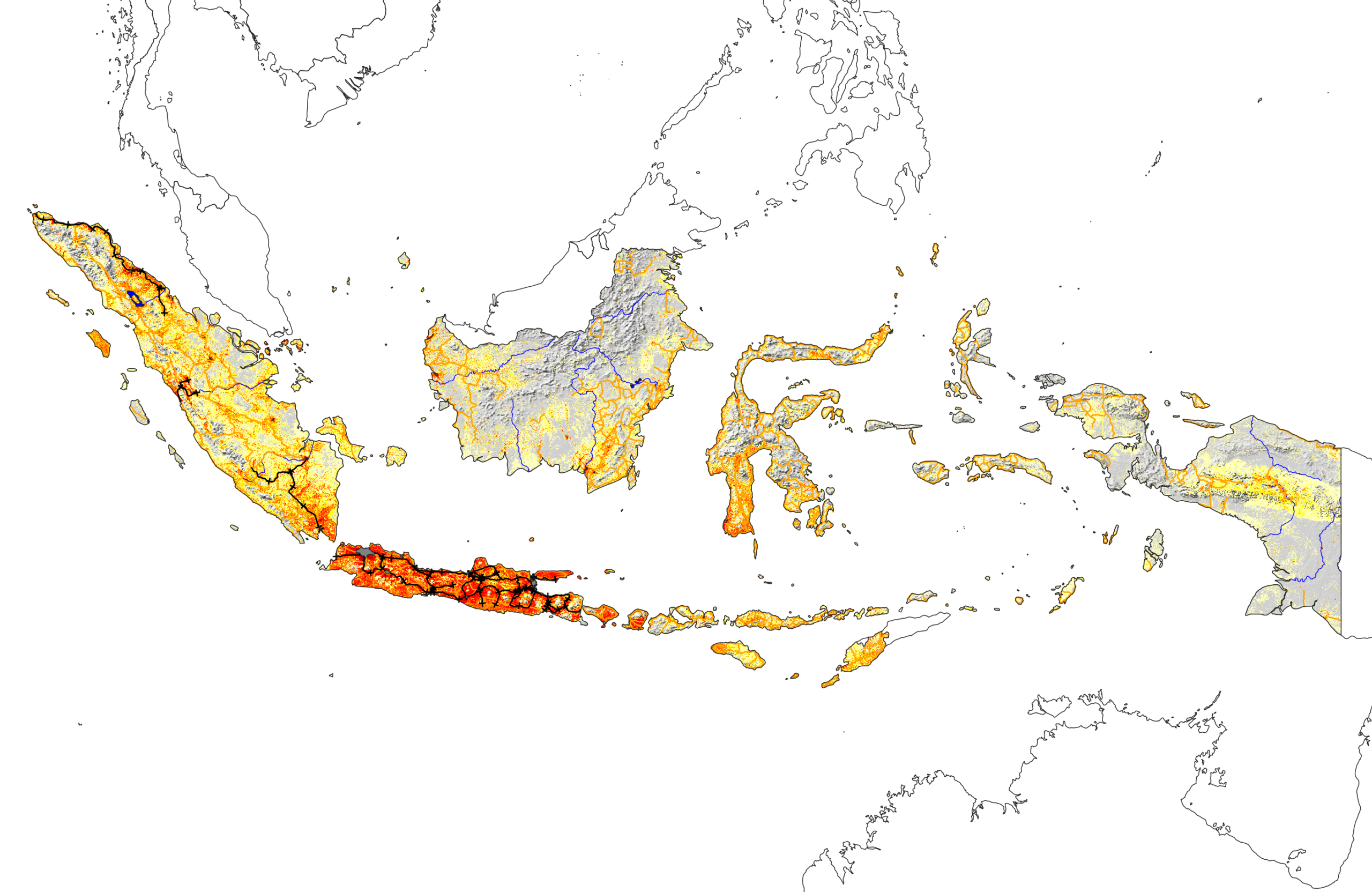
    Indonesia with population and infrastructure

    While there are many islands spread over a large area, the island of Java is clearly dominant in terms of both population and infrastructure. Next is Sumatra to the west of Java, followed by Sulawesi to the northeast. Only Java and Sumatra show railroads, and large parts of Borneo and Papua are sparsely inhabited.

    Nigeria

    Some countries are well known to have large populations, such as China and India. But there are others that have a great deal of people that not everyone is aware of. A good example of this is Nigeria. By far the most populous country in Africa, the extent of people is seen immediately when the population layer is activated:

    Nigeria with population

    A possible reason, broad areas of crops, trees, and grass across the whole country, is also clear to see:

    Nigeria with land cover

    Pakistan is another example of a highly populous country whose map shows it:

    Pakistan with population

    Indonesia is too, although in its case it is less obvious because of the large area of the country compared to the population centers. The United States is similar in that regard.

    Oman

    Finally for population, some countries have almost all people living only in very specific areas. Often these are inhabitants following rivers or being by the coast. Oman is a striking example:

    Oman with population

    Others where the people follow the rivers, the topography, or some other pattern in all or part of the country, are readily found, such as Syria (in the east), and Taiwan.

    Peru

    Moving on from population, some countries have wide ranges of topography, land use, and climate. By spanning the arid coast, through the Andes mountains and into the Amazon rainforest, Peru is one of the best examples, visible if we view the topography and climate zones:

    There are plenty of others showing variety that may be less well-known, such as the more subtle but still-there regions of Italy, or the colder north of Japan.

    Japan climate types

    South Africa

    Finally, let’s view one more country that well exemplifies the overview seen by accessing a range of data: South Africa.

    South Africa: topography, climate, and population

    The topography shows that most of the country is highlands, with lower-lying coasts. But the landscape and climate vary widely, being more barren in the northwest and temperate in the east. The population largely follows this, with the main cities being Pretoria (and Johannesburg), Durban, and Cape Town.

    More

    This page highlights a small fraction of what can be found by exploring these datasets. All the stories and insights seen here can be deepened by further research on a given country. The point of course is to give the level of overview seen for every country, in one place: multiply every layer combination shown above by 258.

    Summary and Future Work

    We have created a process that visualizes each of the world’s 258 countries and regions and allows interesting information to be overlaid. The process of gathering raster and vector layers and clipping them to the desired country is generic and extensible to other data. The results are viewable in QGIS or in a webapp. The processing is done in QGIS/PyQGIS, and the webapp is in Dash-Leaflet.

    While better views may exist for given countries, the key driver here is to get them all in one place, with all layers always available, so the user can explore and learn without bias towards parts of the world that are covered by greater amounts of geospatial data, projects, or companies.

    There are a number of obvious ways this work can be improved further

    • Webapp legend
    • Higher resolution data for smaller countries, especially the borders and digital elevation models (DEM)
    • Cloud-native workflow to tile and serve such larger data at an appropriate resolution for the chosen country being viewed, using formats like cloud-optimized GeoTIFF (COG)
    • Other datasets, e.g., Satellite Embedding V1 from DeepMind’s AlphaEarth Foundations GeoAI model
    • Other information such as industries, geology, mark the capital city, some photos, major attractions, etc.
    • Country-specific CRSs: some countries such as Canada are still distorted in Mercator projection (Ellesmere Island is not that big), and might benefit from a more “looking down at the globe” view, or a country-specific CRS
    • Enable printer-friendly or PDF views for each country
    • Enhance the webapp with pictures, text, etc.
    • Project as a QGIS plugin
    • Combine DEM data and QGIS 3D for a 3D view of each country

    In addition to these, there a range of smaller or technical details in the code, data, and presentation presented in the project’s GitHub repository.

    Note: I have added some of the improvements mentioned above to the GitHub repository since this post was written, along with some others as well. The improvements do not outdate the text here.

  • Finding the Steepest Streets in Millbrae

    Finding the Steepest Streets in Millbrae

    This post is part of my portfolio of personal projects resulting from my transition from generalist data science (2013-2025) to geospatial data science, GIS, and GeoAI (2025+).

    OpenStreetMap and the OSMnx add-on for viewing streets as a network can be used to find the steepest streets in a neighborhood. Loosely based on their tutorial, we find the steepest streets in my home San Francisco Bay Area suburb of Millbrae, make a map of street grades that turned out to be useful for walking the area, and show views looking up the streets via the Google Street View API. The same code can be applied to any named area present in the well-known Nominatim geocoding tool.

    The steepest street in Millbrae?

    Why the steepest streets?

    The main motivations for finding the steepest streets in Millbrae are

    • Curiosity: I live there, and there are a lot of hills to walk or cycle on. Which is steepest?
    • Use OpenStreetMap, OSMnx, and Street View
    • The resulting code is applicable to any named neighborhood

    OpenStreetMap + OSMnx

    OpenStreetMap is the well-known and widely used open source project to provide street maps of the world. Here is provides a suitable base map for us, and is integrated with the second tool we need, OSMnx (docs, citation).

    OSMnx allows you to work with the streets, or more accurately street segments between intersections, to be worked with as a NetworkX MultiDiGraph of nodes and connections, each of which can have properties.

    When the locations of nodes are combined with elevation data, the grade of each street segment can be obtained using OSMnx’s function for the grade along the line segments corresponding to the street segment between 2 nodes. This gives us grades for every street segment in the network, and segment with the largest value is the steepest street.

    OSMnx has an extensive set of tutorials, one of which includes finding steepest streets. The code in this project is loosely based on it, but is mostly original. Some of the lines are:

    G = ox.graph_from_place(place_query, network_type="drive")
    G = ox.elevation.add_node_elevations_google(G, api_key=api_key)
    G = ox.elevation.add_edge_grades(G)
    
    grades_gdf = gpd.GeoDataFrame([d for _, _, d in ox.convert.to_undirected(G).edges(data=True)])
    
    grades_gdf_sorted = grades_gdf.sort_values(by='grade_abs', ascending=False)

    I found some detail improvements in OSM that could be submitted for Millbrae, such as speed limits information and presence of sidewalks.

    Finding the steepest

    OSMnx allows a map of the street network with the street segments colored by grade to be produced straightforwardly:

    Street grades in Millbrae: Yellow are the steepest, through orange, magenta, to purple as the flattest. The hillside running northwest-southeast on the left and the flatter areas next to the San Francisco Bay on the right are visible.

    Interestingly, when first running this project, I was considering doing more walking around Millbrae after dropping our 1-year-old at daycare, and seeing the areas nearby to the northwest of the neighborhood in the above plot with graded but not-too-steep streets encouraged me to do so.

    According to this analysis, the top 10 steepest streets in Millbrae are:

    Geodataframe of Millbrae’s top 10 steepest streets, according to this analysis. The main columns are name and grade_abs, the grade in % (0.18 = 18%, etc.).

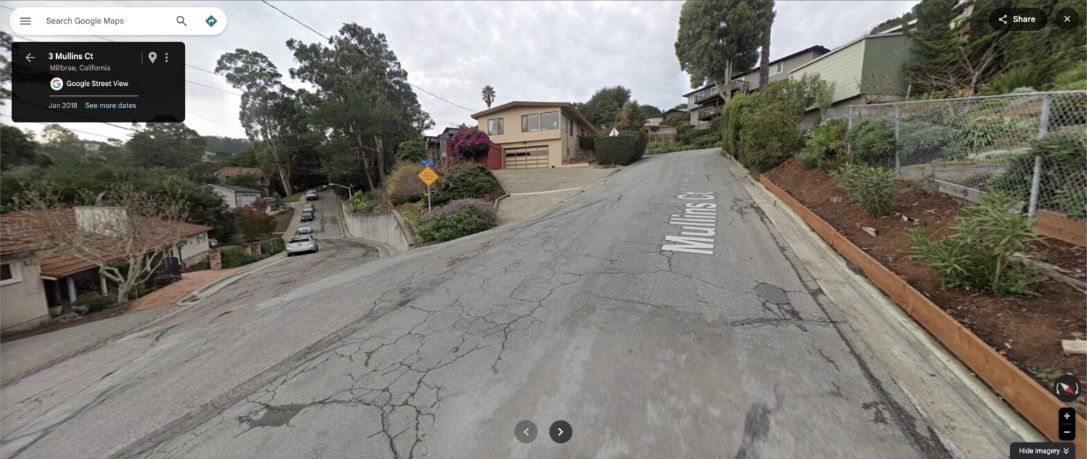
    Now, though, comes a reminder that your analysis is only as good as your data. The steepest street is not, in fact, Mullins Court. The street segment in question happens to be one of very few in the neighborhood that at the time of writing are mislabeled on Google Maps. Having now walked there, I can confirm that, while it is definitely steep, it is part of Aura Vista. This makes sense, as Mullins Court is the no-through street to the west of the intersection. The rest of the top 10 are correct as far as I know.

    We can see the location of the Aura Vista segment as well, either on the street network:

    or with an OSM basemap (with the Mullins Court again mislabeled at the time of writing):

    See it on Street View

    To view the steepest street on Google Street View, we need two steps

    • Access the Street View API at the location of the street
    • Rotate the view direction and angle to be looking up or down the street in question

    After setting up the required API key, accessing the Street View location is achieved by constructing the correct URL:

    URL = (f'https://maps.googleapis.com/maps/api/streetview?size=600x300&location={lat_origin},{lon_origin}'
           f'&heading={heading:.0f}&pitch={pitch}&key={api_key}')

    which for Millbrae looks like this (API key not shown)

    'https://maps.googleapis.com/maps/api/streetview?size=600x300&location=37.5911979,-122.4058984&heading=254&pitch=8.527488864617514&key=<API key>'

    To rotate the view direction and angle, we need to extract and transform the direction and grade of the street segment from the OSMnx network into direction and angle above horizontal to pass to Street View. This is done by considering latitude and longitude for the direction, along with the x and y distances and elevations for the viewing angle.

    Here we always select the view of the bottom of the street looking up. This gives us our view looking up the steepest street segment in Millbrae, as at the start of the text.

    The steepest street in Millbrae, at 18% grade, is Aura Vista. At the time of writing the segment was mislabeled as Mullins Court.

    The approach fails if the street segment has a sharp curve between the two nodes, because you are looking directly towards the next node and not necessarily the direction the street immediately heads. This could be solved by decomposing the segment into its component linestrings and aligning with the first of them, but in practice this rarely comes up in Millbrae.

    Other neighborhoods

    The code is in principle generic to any neighborhood worldwide that can be named in the widely-used OpenStreetMap Nominatim geocoding tool. Simply swap out the name in the settings and explore. Here are some others nearby in the Bay Area:

    Brisbane (San Mateo Lane, 20% grade)
    Burlingame (Martinez Drive, 13%)
    Palo Alto (Mockingbird Lane, 10%)
    San Bruno (Rollingwood Drive, 16%)

    Limits of the data: San Francisco

    As is common in GIS, however, the real world has a way of bringing on limitations on workflows that naively seem straightforward, often in instructive ways. In this project, we see it if we set the place considered to be not a medium-sized suburb, but the whole of San Francisco.

    Because of its many steep hills, streets navigating them, and large size, San Francisco is particularly prone to street segments with spurious grades:

    • Limited latitude + longitude accuracy of the elevation data results in street node points on hillsides close to the street, not on the street
    • Very short segments of only a few meters connecting one-way halves of streets at an intersection (common in San Francisco)

    The grades plot itself looks good:

    San Francisco street grades

    but it thinks that this wall is the steepest street (71% grade!):

    “The steepest street in San Francisco”. This is a spurious steep grade created by slight inaccuracies in the locations of the elevation nodes compared to the local topography.

    Appropriately the name of this “street” is NaN.

    There are some detail ways that these artifacts could be reduced:

    • Filter out any segments of obviously spurious grade, say over 40%, and too-short length, say less than 10 meters
    • Manually inspect remaining Street View images
    • Manually adjust street node points so they correspond to the satellite image of the intersection (being sure that the network and raster are precisely aligned using a local CRS projection)
    • Remove the OSMnx default consolidation of intersections, which may over-simplify some short steep segments

    Ultimately addressing all of these in detail would constitute a full research project.

    Summary & Future work

    We found the steepest streets in my local neighborhood of Millbrae using OpenStreetMap and OSMnx, and viewed each one using Google Street View. The steepest street is Aura Vista, with a grade of 18%.

    The code can in principle be run on any neighborhood worldwide that is named in the well-known Nominatim geocoding tool.

    The main improvements to the results here would be

    • Make a webapp so users can see their neighborhood without writing code
    • Refine the analysis to be more robust in places such as San Francisco, using the ideas detailed in the main text above
    • Share it directly to target communities, e.g., OSM User Diaries
    • Add an option to use Open Topo data instead of Google elevation data so that the code can optionally be run without requiring the user to set up a Google API key

    There are smaller improvements as well. For example, normalizing the grades colormap to be absolute and not calibrated to only the range of grades in that neighborhood. As currently coded, for example, somewhere very flat like Foster City would still show yellow for the streets with the highest grades, even though those grades are not high. The GitHub repository has the full set of ideas.

    Interestingly, one consequence of these improvements might be, if a minimum threshold length for consistent grade is introduced to remove short street segments, such as the short ~ 10m segments of Hillcrest in Millbrae that place second and third, this might result in the 65m Aura Vista getting dropped, and the much longer (307m) but almost-as-steep Larkspur Drive taking the title. The whole segment between Pinehurst Court and Crestview Drive has an average grade of just under 16%, and in a way is a much worthier steepest street. Ultimately it depends on what we would like to highlight as a steep street.

    Larkspur Drive: the real winner?

    Note: I have added some of the improvements mentioned above to the GitHub repository since this post was written, along with some others as well. The improvements do not outdate the text here.

  • Mapping a Historical Tour of Sheffield’s Don Valley, where the World’s Steel Industry Began

    Mapping a Historical Tour of Sheffield’s Don Valley, where the World’s Steel Industry Began

    This post is part of my portfolio of personal projects resulting from my transition from generalist data science (2013-2025) to geospatial data science, GIS, and GeoAI (2025+).

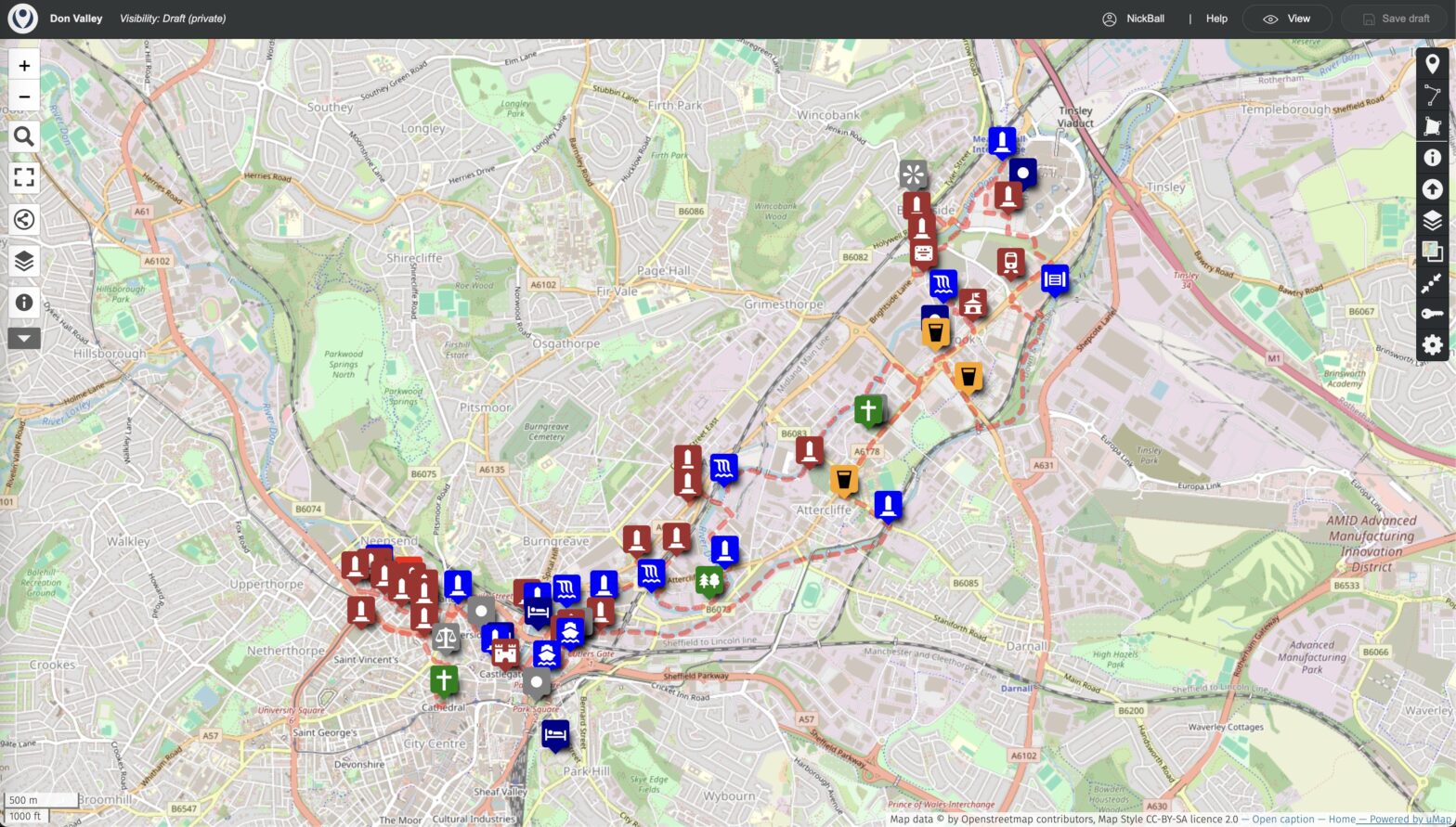
    My brother Andrew wrote a walking tour of the historical roots of the modern steel industry, Sheffield’s Don Valley for his blog. The open-source software uMap with an OpenStreetMap base can be used to turn this into a visual tour with a map, walking route, text and photographs. uMap can be used similarly for any piece of writing that involves traveling around an area. The map is available here .

    Don Valley walking tour route and locations on uMap with OpenStreetMap basemap

    Don Valley

    Extending northeast from Sheffield City Centre, Don Valley is an area of global historic importance because of the history of the Sheffield steel industry. This encompasses its origins, the invention of stainless steel, and the manufacture of many products, the most well-known of which is cutlery.

    Why map it?

    Sheffield is a large modern city that has moved on since these industrial days, and so viewing such history in-place today requires knowing where to look, and what you are looking at. What you need, in other words, is a guide, and Andrew’s walking tour provides this.

    The original tour is a text document that is nice to read and well researched. It is, however, only text, and so unless you know Sheffield very well already, or walk the tour in-person, there is a certain amount of abstraction to the history described.

    For this reason it benefits from adding a map:

    • Visualize the locations
    • Show the walking route
    • Incorporate text into the map
    • Add pictures

    Furthermore, the approach taken is generic: any text that involves describing places could be mapped in the same way.

    uMap

    uMap provides an open source solution that allows geospatial locations (points, lines, and polygons) to be overlaid on a street map base. It is built on top of the widely used Leaflet mapping software.

    uMap is generally used in a no-code fashion, although GIS knowledge, use of markup, etc., is useful for more advanced features.

    Making the map

    We start by selecting the basemap, OpenStreetMap in English, and an appropriate center and zoom level. The center is the start of the walk at Sheffield Cathedral, and the zoom is to Don Valley.

    Then we use the points datatype to add the locations mentioned in the text, formatting with various properties such as name, icon type, color, etc.

    Editing a point: Kelham Island Museum

    The walking route is added using the line datatype, following paths where they are marked, and placed in the road center where they are not. Sidewalks are not generally marked on the basemap used, likely because its maximum zoom level is not as high as the original OSM. The linestring resulting also has nodes in some places with more than two lines intersecting, because the route loops and returns to places already passed.

    Editing a line: walking route west of Tinsley locks

    We did not use the polygon datatype on the current map. It could be added, for example to show the outlines of buildings of interest, but there was sufficient content already for our purposes.

    Likewise we used the simple default symbology available in the uMap GUI, without, e.g., addons of icon types or symbols.

    A nice feature of uMap is that it allows points to be labeled with media such as text, pictures, or video, activated in various ways such as clicking on the point. This allows pictures of the locations to be added, or even the entire original blog text appropriately spaced. Currently each point has a simple label and the text is the original blog entry.

    Details, details…

    So this is all fairly easy, right? Just read a few pages and add some map points. Well, nope. As you might expect with the real world (and especially GIS), some things come up.

    A particular example from this walking route was on the Five Weirs Walk. Andrew’s original route had you following it for some distance, but since the text was written part of the walk between East Coast Road and Attercliffe Road has collapsed into the river. If you like climbing steep grass embankments with trees and old pieces of concrete it might still be possible, but for normal people we need a reroute round the streets.

    The first step was to confirm that it was closed. Google Maps shows the path as still there, labeled Five Weirs Walk. Apple Maps shows the path, unlabeled. But the OSM base map shows closed gates and the segment of the path no longer present. On the satellite images, on both Google and Apple the collapsed section is visible, with the river extending close to the wall on the west bank, and pieces of concrete in the river. Not much is visible from Street View.

    To reroute round the closed section, from Google Maps you might naively choose Windsor Street, but Apple Maps hints you may not want to because the street is marked narrowly as not a regular street, and indeed OSM and StreetView show that it passes through the premises of Thessco Ltd. At the other end there is a gate blocking the way to Princess Street, and it kind of goes near the Five Weirs Walk again but is behind the gate on that path. So maybe you can still walk through, but simpler is to route across the river around Faraday Road and Washford Road, which are regular streets.

    The obvious step if you really wanted to go along Windsor would be to go there (or have Andrew go there), but it’s not necessary to do that here.

    Addressing details like this routing ideally results in a route you can walk in-whole or in-part.

    Some places along the route

    The full route is on the map, but a few highlights are below.

    Bower Spring: These are the best preserved remains of a mid-19th century cementation furnace, the process that enabled production of steel in quantity and put Sheffield on the map as a world center. It was recently restored and removed from the Heritage at Risk list in Yorkshire, which was reported on by the BBC in this article.

    Bower Spring cementation furnace. From the BBC news article.

    Kelham Island Industrial Museum: Showcases the history of the steel industry in Sheffield, along with other exhibits. The 12,000 horsepower River Don Engine that was used to roll steel plate is regularly run and has the shortest time to reverse direction of a machine its size anywhere.

    Kelham Island Industrial Museum. From Google Street View.

    Ball Street bridge: Aside from being my namesake, this is a scenic bridge over the River Don, giving good views of the river and former works on the banks such as Alfred Beckett and Sons.

    Ball Street bridge. From Google Street View.

    Birthplace of stainless steel: This building used to house Brown-Firth Research, and was the world birthplace of stainless steel, one of the materials that revolutionized manufacturing in the 20th century due to its lack of rusting.

    Birth place of stainless steel. From Google Street View.

    Terry Shellby, canal terrapin: Not officially part of the tour, but found along the way.

    Terry Shellby canal terrapin. From Google Maps.

    Can AI make this map?

    The short answer is no, not yet. While the latest foundation models and coding tools (Google’s Gemini 3 and Claude Code at the time of writing) can help make maps from a prompt, and do other agentic work, the material here is too esoteric to work well. Places such as the sites of old steelworks not now named on the basemap need to be appropriately placed, and actually-possible routes like not taking the part of the Five Weirs Walk that has collapsed into the river need to be given, plus the suitable rerouting round a street mentioned above.

    What AI could likely provide is a rough draft map or list of locations from the text, and help with creating a map with the uMap API if you prefer that route to the no-code one. It could also provide a handy summary of the text, an interface to answer questions about it, further pictures or links about places of interest, and how to travel there. But it is not going to outdate the full manual work to create this project just yet.

    Summary & Future work

    We have made a map of a walking tour of Don Valley showcasing the globally important history of the steel industry present in the area. The original walking tour text is here, and the map is here.

    The map is made in a no-code fashion using the open source software uMap using an OpenStreetMap base. The emphasis is on the content and making a visualization of sufficient accuracy that it can be used as a guide to walk the route.

    Some improvements to the work include

    • Add pictures and text to the points
    • More extensive symbology
    • Have someone walk the route to confirm it is 100% correct

    The uMap approach is generic, meaning that any text that describes travel around locations could be mapped in the same way.